This is a continuation of my adventures in building a custom Eurorack modular synth case. Go back Part 1 – The Design, Part 2 – The Woodwork, or Part 3 – The Assembly, or skip ahead to the last chapter at Part 5 – The Setup. If process stuff isn’t for you but experimental music synthesis is, cut right to what this dang thing sounds like.
OK. So the wood was tricky, but this part will be tricky also. I’ve built some tube guitar amps, tons of effects pedals, and soldered hundreds of audio cables in my time so I’m decent with an iron and know my way around a circuit diagram.
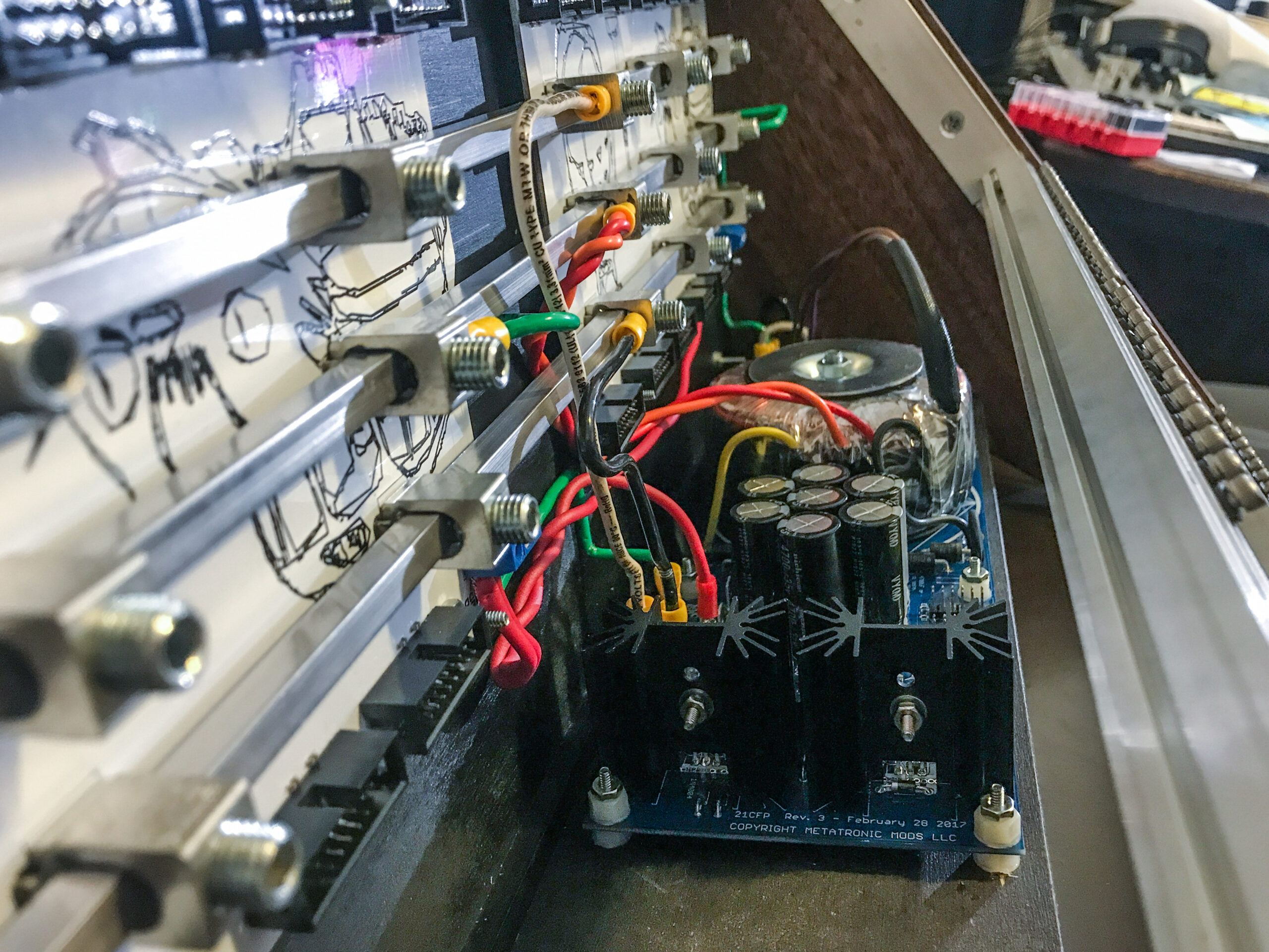
I went with the Metatronic Mods DIY Power Supply because it had solid output ratings for +12V, -12V, and +5V, it was a linear power supply instead of switching, and it looked like a well designed and filtered unit. I needed something with 5V because several of the modules I planned for require it and I didn’t want to fuss with my own DIY stepdown from 12V to 5V.
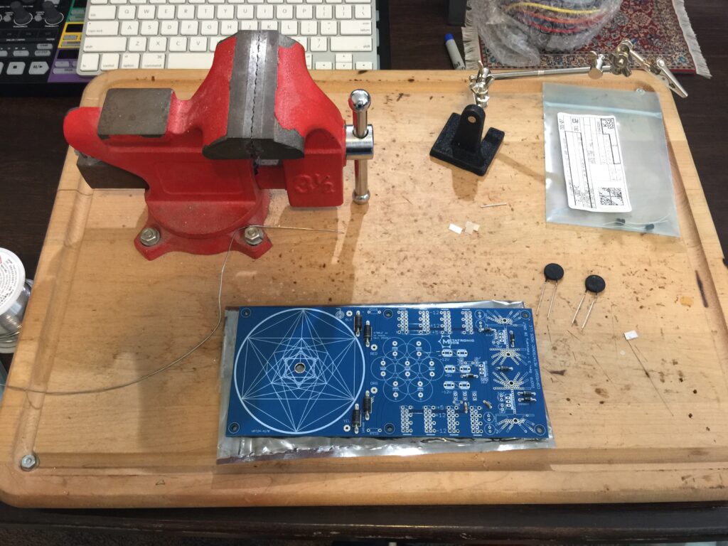
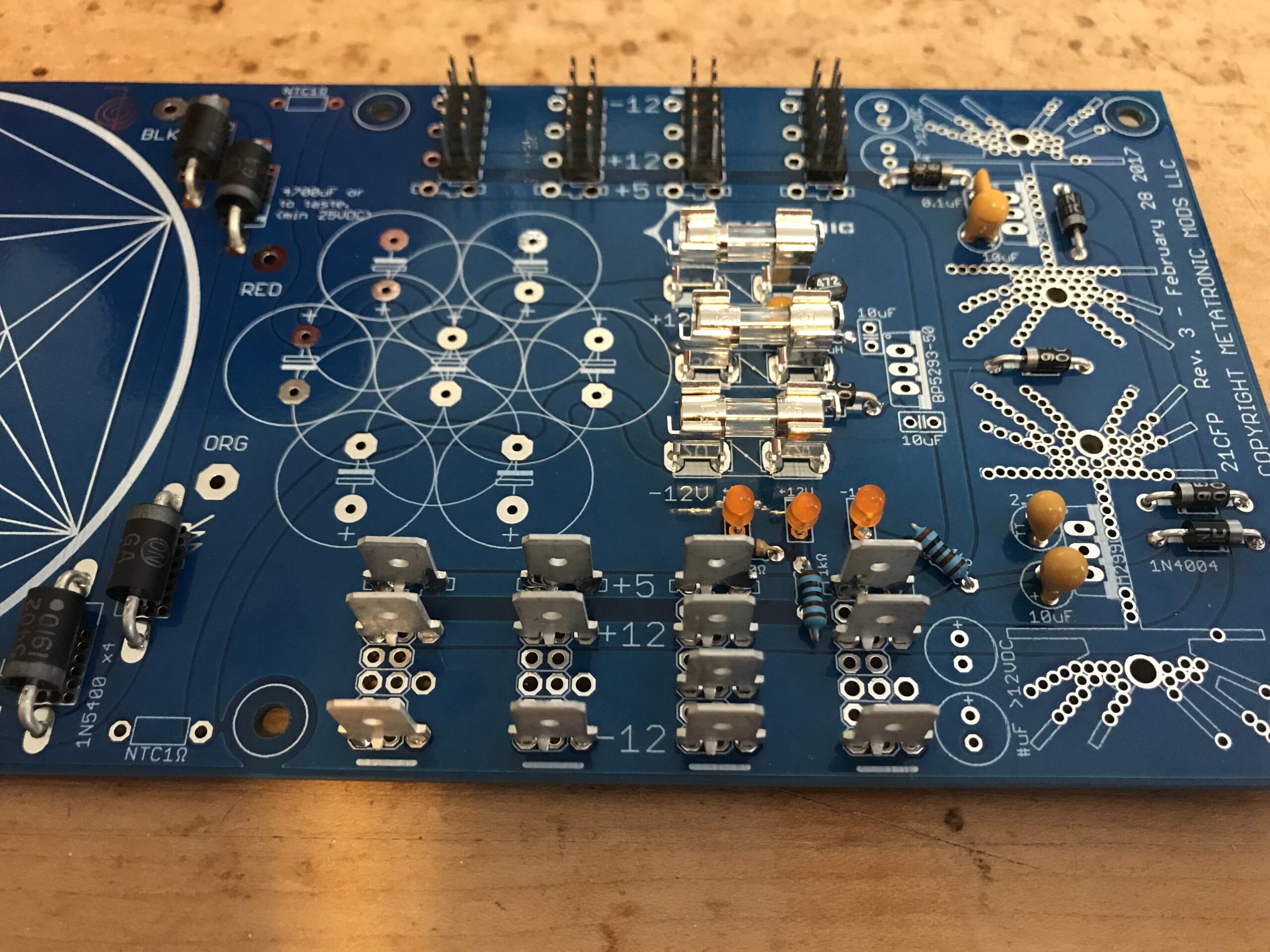
The circuit board for this thing is really nice. It’s very well laid out for a DIYer and it came with a great build guide that only required a bit of sleuthing to figure stuff out. There was a component indicator that was hard to read, and a couple bridges were indicated on the backside to add some nice-to-have circuit features but other than that it was pretty paint by numbers. I also went with their bus-bar distribution components because….it looks really cool. I don’t fully understand the electrical theory behind it (ask Graham Hinton) but I do know bus bar designs are frequently used in large building electrical plants so it’s probably good for something.
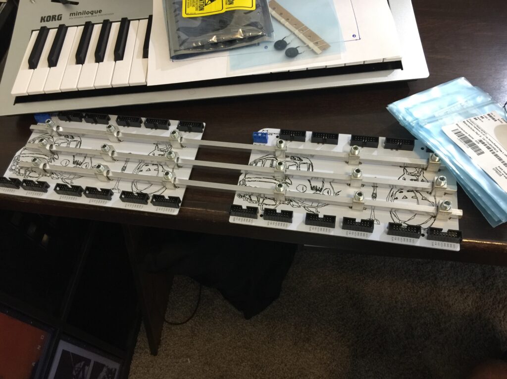
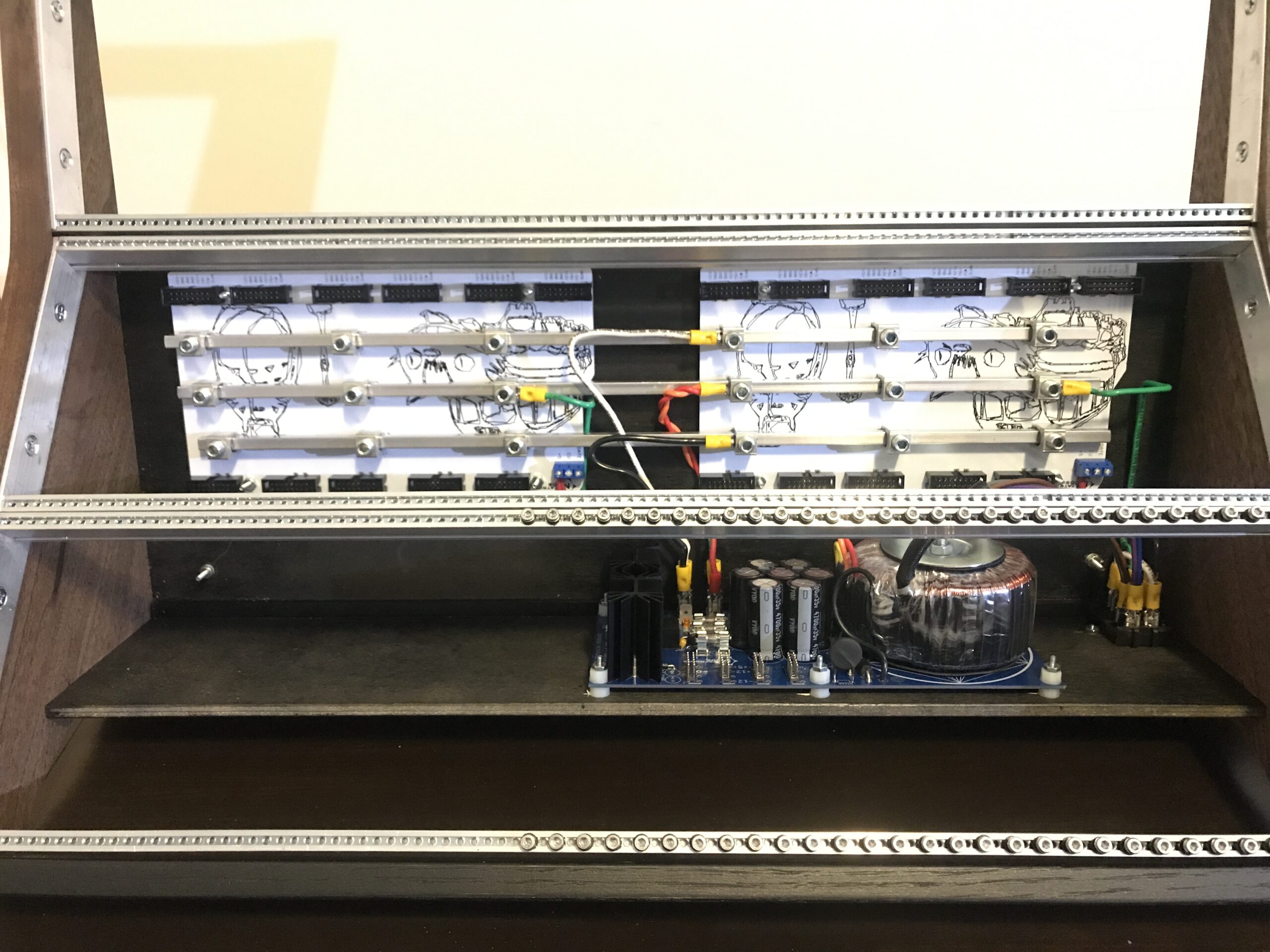
I elected to go with clip headers on the bottom side of the PSU for connecting the main wiring to the bus bars, and then 16 pin headers on the top side in case I needed extra ports beyond the 20 that come with the distribution board.
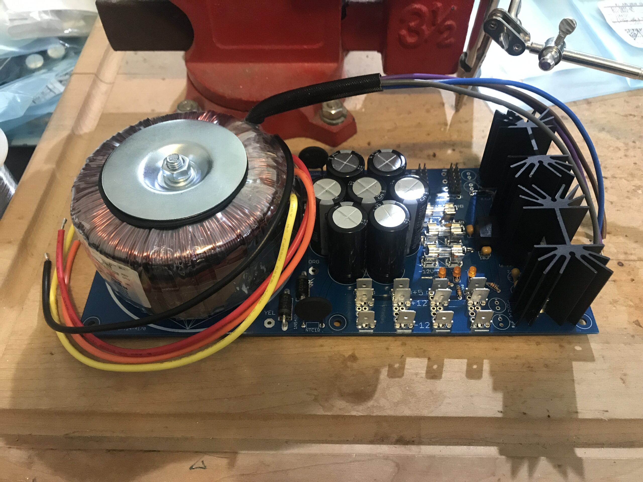
Finished PSU with transformer, voltage regulators and their heatsinks, and the electrolytic capacitors mounted.
I’ll tell you what, mounting this thing into the case wasn’t terribly fun because I didn’t bother to print out templates of the drill holes, because I thought I’d just be able to use the actual parts. In retrospect, I would have gone to the trouble of figuring out the scaling to correctly print out some templates, and printed the templates, and used them. But after a little bit of increase-that-hole-size here and there, I got them fitted.
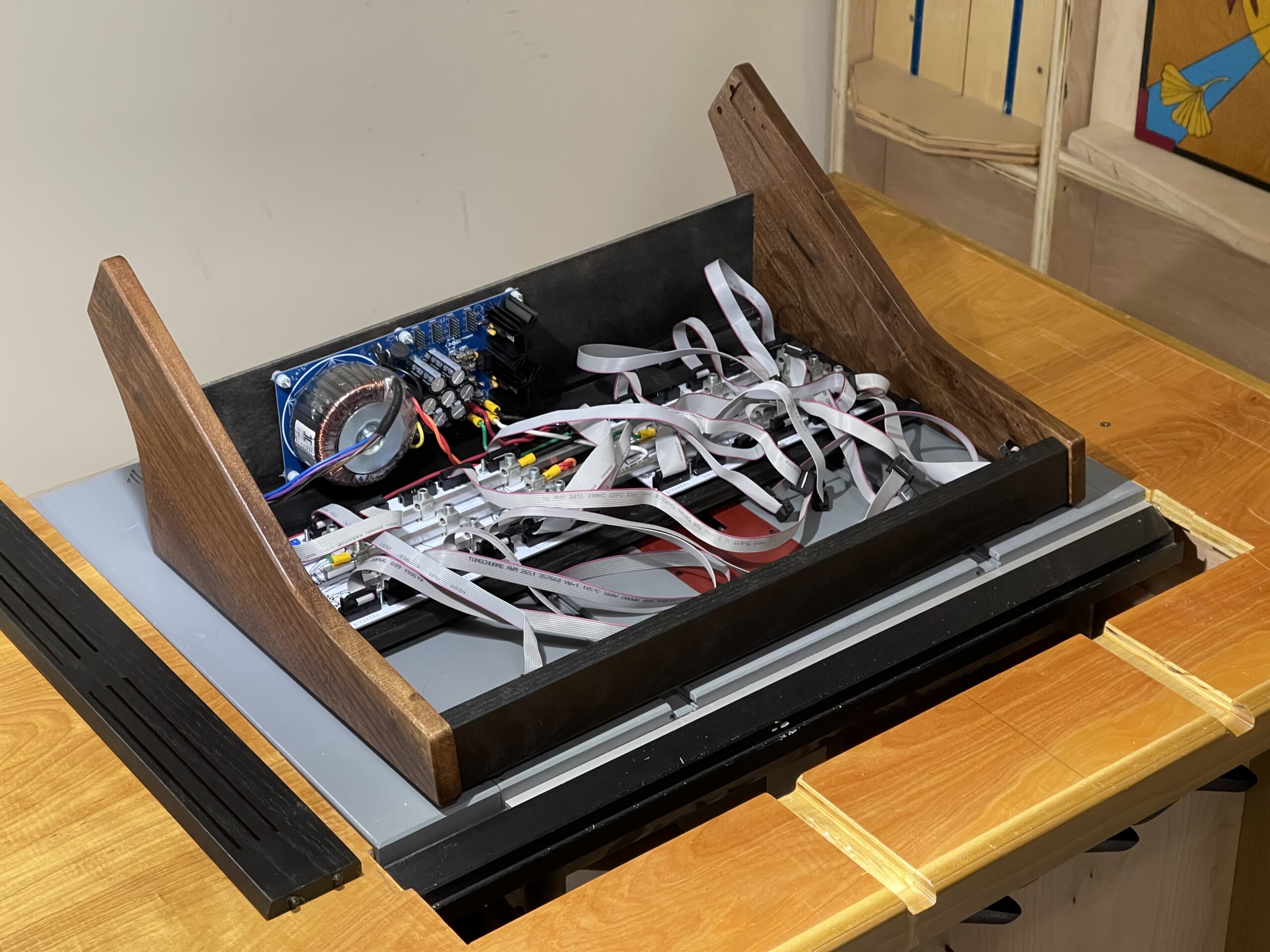
It’s a tight fit once the rack rails are installed, but perfectly accommodates the 2″ module depth I was looking for in all locations across all the racks. Something that happened to work out in this build but that I didn’t consider in the design was that when cables are plugged into the headers on the distribution boards, those cables stick up further. Fortunately that didn’t crimp into any of the 2″ clearances anywhere.
I wired them up to have a switched IEC power connector because there is nothing more annoying that a piece of equipment not having an on-off switch.
Now for the moment of truth. Firing it up for the first time. I suppose I was cavalier in mounting this thing in here before powering it on first. But I did run some continuity tests and everything looks good (no shorts or weird continuity where it wasn’t supposed to be) so I figured lets go for it.
A trick I learned from my tube guitar amp building days is to fire up a new build for the first time using a lightbulb limiter. This is a DIY device you can build that puts a lightbulb in the conductor path of the hot connector of a power cable, then makes an outlet available to plug stuff up to. If there are shorts or the build is drawing too much current for some incorrect reason, then you’ll burn out the light bulb (or it will glow very brightly) before burning out any components in the build, and you can begin troubleshooting what you did wrong. So I used my LBL to fire these builds up for the first time.
AND IT WORKS! Or, at least the lightbulb didn’t blow out. Awesome.
A quirk of the Light Bulb Limiter approach is that when your device is getting power from it, none of the voltage readings in your circuit will be correct because its expecting 120V from the wall but instead is getting something significantly less through the lightbulb. So in the case of this eurorack power supply that meant that the LED lights (that indicate that each power rail is pushing current) don’t actually glow.
So the next moment of truth is to remove the Lightbulb Limiter from the equation, plug this directly to the wall, and hope I don’t burn the house down.
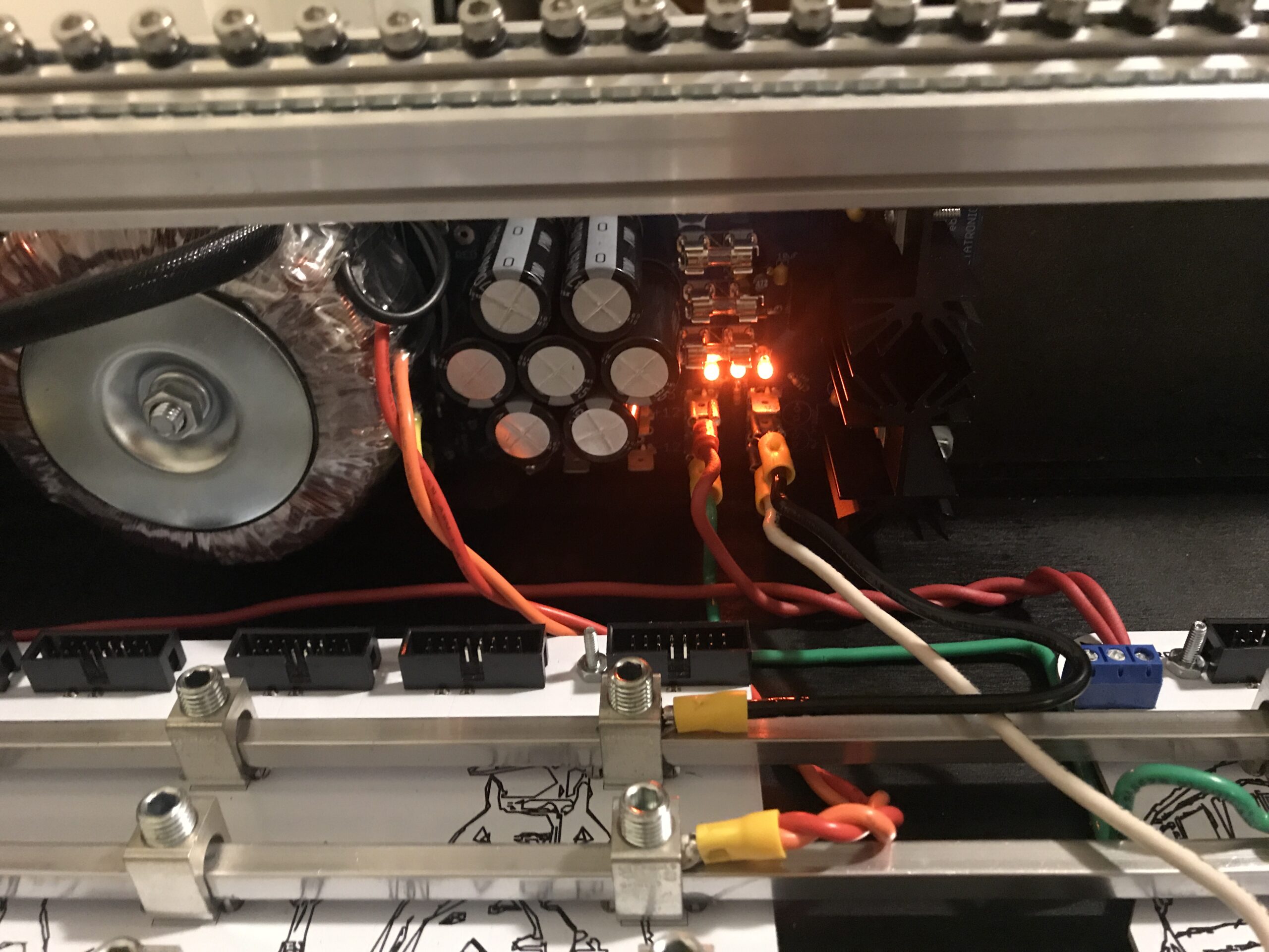
Success! And now, I can check that all the power rails are reading the correct volts, and the pins on the distribution boards are reading the correct volts.
Now we still have to plug some modules up to this thing I just hacked together and hope they don’t burn up for some mysterious-but-low-current reason.
Next up: Part 5 – The Setup