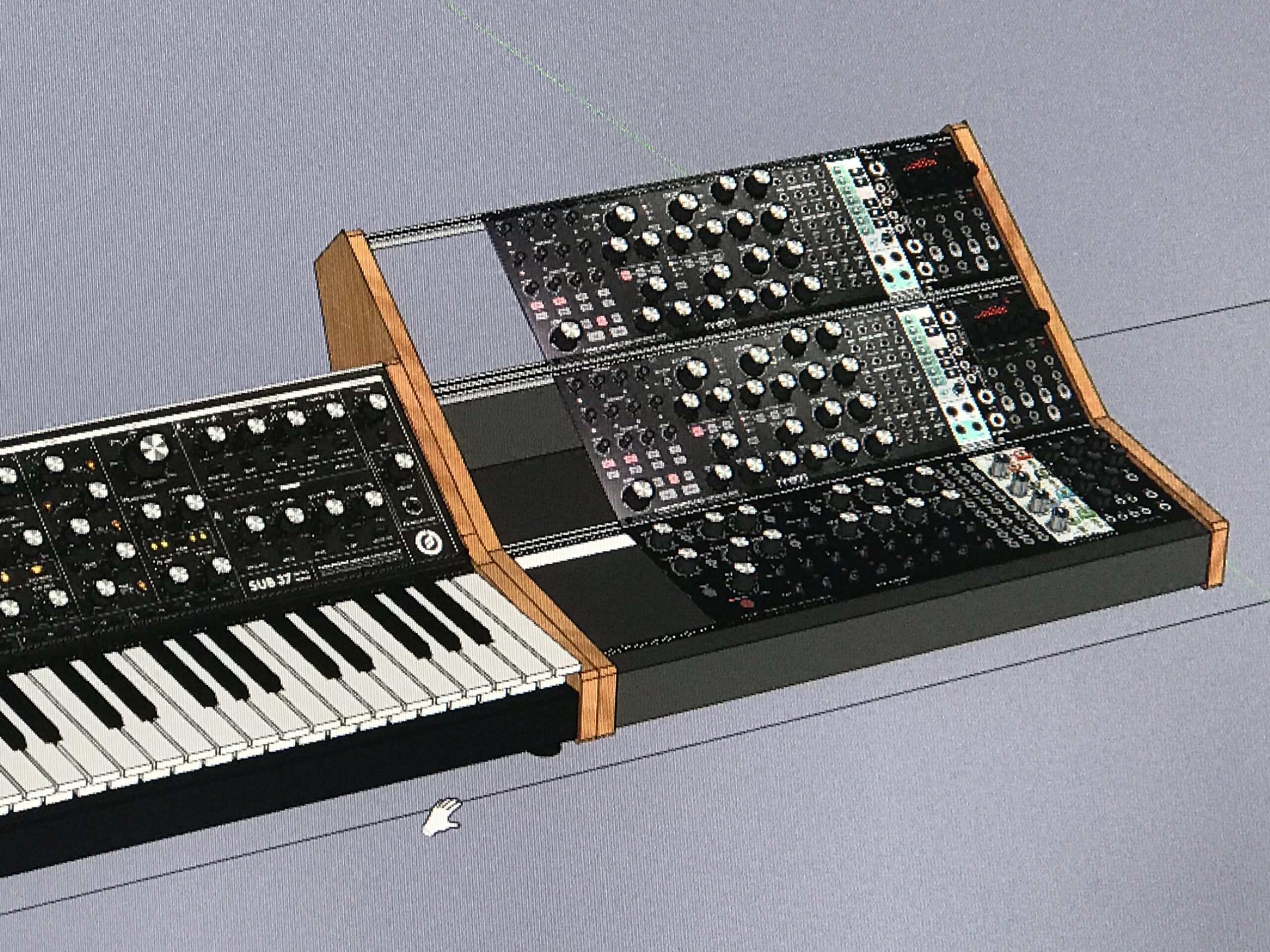
As I was getting into eurorack modular stuff, I realized that this was the perfect intersection of my passions for making music, DIY electronics, and DIY woodworking. So I set out to build a fairly compact eurorack case that would match my Moog Sub 37’s profile so the Sub 37 and the euroracks looked like good companions in my project studio. It turned out to be harder to source the parts than I expected it would be. More deets here on the eurorack format, my design choices, and this particular setup.
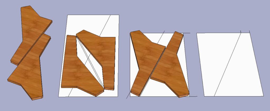
I always plan everything I build in the 3D design tool Sketchup, which I’ve been using since my architecture days. I elected to make the end panels for these racks out of a nice walnut, and this also helped me plan how I would cut the walnut board to efficiently get the four end panels I wanted out of it.
The design challenges here were that I wanted to have clean end panels, free from screws, bolts or other hardware. I also wanted it to match as closely as possible the profile of my Moog Sub 37 synth, while still allowing for enough module mounting depth to accommodate modules that were 2″ deep at least. Finally, I wanted it to have a pretty serious non-switching power supply that was internally mounted. Cool!
The Design
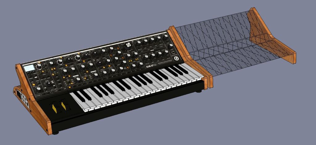
I elected to use a configuration with 3 rows of 3U at 104HP. I tried a few different widths and configurations, but that was the best balance between module capacity and desktop space for me.
A configuration that was 2 rows of 3U with a 1U row in between would have matched the profile of the Sub 37 exactly and I almost went with that config, but the layout just didn’t seem as functional for what I wanted. I may still end up building a rack in that format though, stay tuned.
I used the invaluable tool at Modular Grid to work on the custom layouts and plan the case. Here is the case I planned the build around, and you can see other cases and racks I’ve planned here.
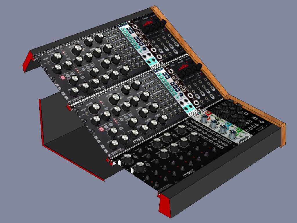
You can see in the above Section diagram that I created an “L” profile bottom and back section so mount the power supply and distribution in, but left the top-rear and the bottom-front open. This is both for air ventilation and to maximize the depth of module that can fit in, with an added bonus that it makes the cases weigh a little bit less also. The downside is that the backs of the modules (the sensitive circuit-board bits and power connectors) are exposed and vulnerable should the case be moved. That’s ok with me because I won’t be transporting these cases much at all.
Once I had the design down, I wanted to plan out how I’d cut the end panels out of the walnut board I had purchased. I wanted to use it for a couple projects so I wanted to be frugal with how I cut it up and used it. Since it was about $100 for a single 7′-0″ x 1′-0″ board, I needed to be careful to get my money’s worth out of it and minimize waste. So I planned out the most efficient way to get the end panels out of it while still having the wood grain run on the end panels the way I wanted (more or less longitudinally).
The other parts are going to be made out of red oak (for the front and rear rails) and 1/4″ plywood (for the “L”-shaped bottom and back) so planning the cuts on those parts weren’t as important. That said, cutting the nose on this front rail is going to be a real challenge since it’s a thin dimension, and only has one 90 degree angle. It’s gonna be fun!!!
Next post: Building a DIY Eurorack Modular Synth Case, Part 2 – The Build